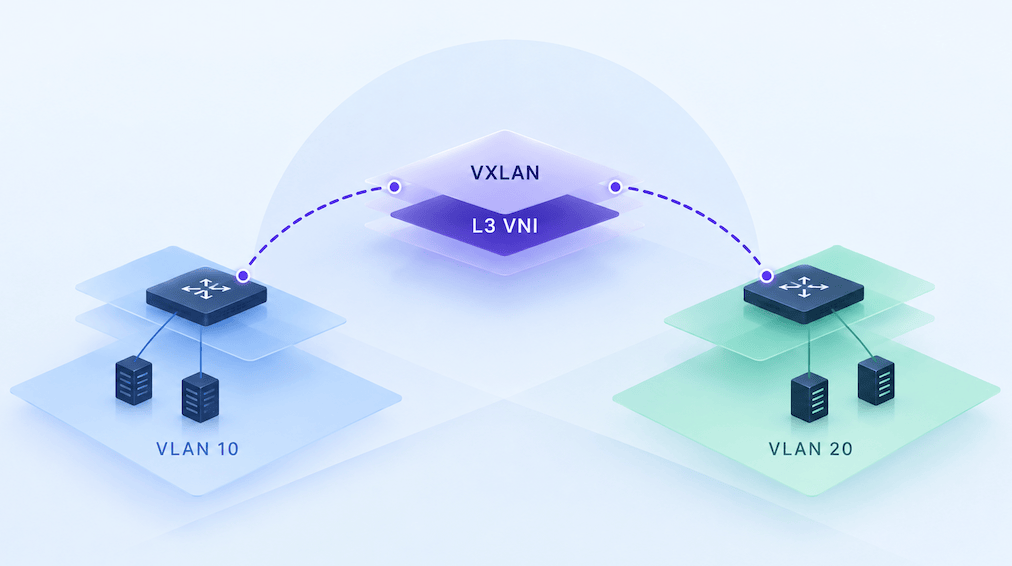
EVPN-VXLAN can seem unnecessarily complicated until you stop looking at all the individual protocols and start following a packet through the network.
IRB, or Integrated Routing and Bridging, allows a leaf switch to provide both layer 2 bridging within a subnet and layer 3 routing between subnets. In an EVPN-VXLAN fabric, there are two primary ways we can do that known as asymmetric and symmetric IRB.
So, to understand symmetric IRB and how it compares to asymmetric IRB, let’s do a packet walk through an EVPN-VXLAN fabric.
Asymmetric IRB
Suppose Host A is connected to Leaf 1 in VLAN 10, and Host B is connected to Leaf 2 in VLAN 20.
Host A can’t send directly to Host B because they’re in different IP subnets, so we need to do some routing. Host A sends the packet to its default gateway on Leaf 1. Leaf 1 performs a Layer 3 lookup and learns that the destination is reachable through VLAN 20.
That’s basic networking so far, except that Host B isn’t connected to Leaf 1.
Therefore, Leaf 1 encapsulates the resulting Ethernet frame in VXLAN using the L2 VNI associated with VLAN 20 and sends it across the fabric to Leaf 2. Leaf 2 decapsulates the packet and performs a Layer 2 lookup to deliver it locally to Host B.
So the forwarding operation looks something like this:
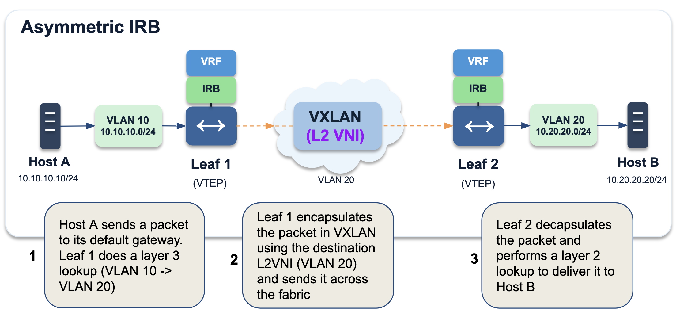
That’s asymmetric integrated routing and bridging, or asymmetric IRB.
Now let’s look at the return path.
When Host B responds, Leaf 2 performs the routing operation and Leaf 1 performs the final bridging operation.
So think about it. That means Leaf 1 needs enough information about VLAN 20 to forward the packet toward Host B, even though VLAN 20 may not have any locally attached hosts. In other words, for Leaf 1 to forward packets to any VLAN that’s not local, it needs to know about that VLAN.
RFC 9135 describes this in more detail, but the practical consequence is that VTEPs using asymmetric IRB need MAC-VRFs, bridge tables, IRB interfaces, and remote host information for the relevant subnets. As the number of VLANs, VNIs, and endpoints grows, that can become very significant.
Symmetric IRB
Symmetric IRB changes where the routing happens.
Using the same example, Host A sends traffic destined for Host B to its default gateway on Leaf 1. Leaf 1 performs a Layer 3 lookup, but instead of routing the packet directly into Host B’s L2 VNI, it forwards the traffic across the fabric using a Layer 3 VNI (L3VNI) associated with the tenant VRF.
If you’re already familiar with L2VNIs, think of the difference this way. An L2VNI identifies a Layer 2 broadcast domain, similar conceptually to a VLAN. An L3VNI identifies a Layer 3 routing domain and is associated with a VRF. With symmetric IRB, we’re using that L3VNI to carry routed traffic between VTEPs rather than extending the destination VLAN to the ingress VTEP.
The VXLAN packet is sent to Leaf 2, where something important happens.
Leaf 2 doesn’t just bridge the packet toward Host B. It performs another Layer 3 lookup within the VRF, determines that Host B’s subnet is locally attached, and then forwards the packet into the appropriate local VLAN.
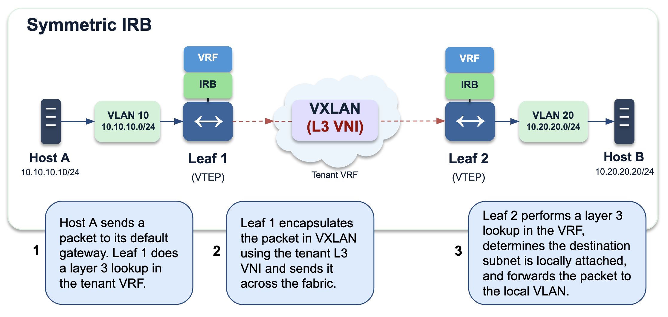
Now the operation is symmetric. Both VTEPs participate in the Layer 3 forwarding process. This is inter-subnet forwarding between the IP-VRFs of the two PEs rather than between their MAC-VRFs or bridge tables (a PE is just the provider edge router or switch at the edge of the network fabric that acts as a VXLAN Tunnel Endpoint, a.k.a. VTEP).
This difference between asymmetric and symmetric also changes what has to exist on every leaf.
With asymmetric IRB, the ingress VTEP needs forwarding state associated with the remote destination subnet. With symmetric IRB, each leaf generally only needs the L2 VNIs, VLANs, and associated host state for networks that are actually local to that leaf. Remote networks can instead be represented through Layer 3 routing information in the tenant VRF, which is a much more scalable model.
Why Symmetric IRB?
Imagine a small EVPN fabric with four leaf switches and ten VLANs. Configuring every VLAN and L2 VNI everywhere probably isn’t a major problem. But now imagine hundreds of leaf switches supporting hundreds or thousands of tenant networks. Requiring every VTEP to maintain Layer 2 state for every network becomes much less attractive.
Symmetric IRB lets us keep Layer 2 forwarding relatively local while using Layer 3 forwarding between VTEPs. The L3VNI effectively provides the routed connectivity between the distributed instances of a tenant VRF.
So in effect, an L2 VNI represents a broadcast domain, and an L3 VNI represents a routing domain.
Traffic staying within a subnet can remain within its L2 VNI. Traffic crossing subnet boundaries is routed into the tenant’s Layer 3 domain, transported across the fabric, and then routed by the destination VTEP toward the locally attached subnet.
Yes, this does mean more configuration compared with asymmetric IRB since we now have tenant VRFs, L3VNIs, router MACs, and the associated EVPN control-plane information to think about. So asymmetric IRB can actually still make sense in smaller or simpler environments where scale isn’t a major concern.
But for larger EVPN-VXLAN fabrics, symmetric IRB gives us the ability to scale Layer 3 connectivity without requiring every leaf switch to participate in every Layer 2 network.
So if you remember nothing else, remember where the packet crosses the fabric. With asymmetric IRB, the ingress VTEP routes the packet into the destination L2VNI before sending it across the fabric. With symmetric IRB, the ingress VTEP routes it into the tenant’s L3VNI, and the destination VTEP routes it into the locally attached subnet.
Asymmetric: route, then cross the fabric at Layer 2.
Symmetric: route, cross the fabric at Layer 3, then route again.
Once I understood that packet walk, symmetric IRB became a lot less complicated.
Thanks,
Phil


Leave a comment