
There are a small variety of methods to implement failover of your WAN perimeter between two ISPs. In this post we’ll look at one way to accomplish this goal with a few technical requirements.
Keep in mind that there are several ways to accomplish this same goal depending on the hardware available, the flexibility of the ISPs, and the skill level or preference of the engineer.
This topology utilizes two edge routers and two ISPs instead of the single edge router design I wrote about recently (you can read that here). For this post we’re using Cisco routers, but the concepts apply universally. Our requirements are that we maintain connectivity from our inside host to the internet in the event one of the company routers fails or one of the ISPs fails. Failover and fail-back must be automatic with no manual intervention.
I’ve created our testing topology like this:
- The public internet is represented by several loopback addresses on a router named Internet
- Our inside host for testing is a loopback address configured on a router called R_1
- Our pair of edge routers are called R_2 and R_3
- The ISP routers are ISP_A and ISP_B and are connected to simulate the multiple paths to a destination on the public internet
- The ISP routers and Internet all have eBGP relationships with each other
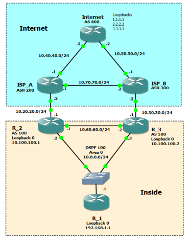
On Internet I configured three loopbacks that we will use to simulate public internet reachability. On R_1 we have loopback0 to simulate a simple LAN network. I also created a loopback on R_2 and R_3 for iBGP peering. For this design I used a switch in order to create OSPF adjacencies between Routers 1 through 3 off of one interface on R_1.
Before we get into the configuration, let’s review the design from the LAN out.
Using OSPF between routers 1, 2 and 3 provides multiple paths to either ISP. You can also use HSRP or VRRP to create an active/standby relationship between the two corp routers, but in this case I want to base all our path selection decisions on routing metrics. We’ll adjust the metrics in order to prefer R_2 and ISP_A.
Our corporate autonomous system number is 100 which will be used for the BGP peer with both ISP_A and ISP_B and internally between the two corporate routers. We also need to establish an iBGP peer between our two corp routers in order to create a full route exchange. This is what gives us backup paths to internet destinations; however, we’ll need to make sure we advertise prefixes correctly out to each ISP so that we don’t accidentally become a transit path for the public internet. The iBGP peering will use the loopbacks on R_2 and R_3 and will utilize OSPF for actual reachability.
In this design each corporate router is peering with only one ISP, but another option is to have each corporate router peer with both ISPs. I won’t be filtering inbound, and in a production network using this or a similar design, I would try to spec routers that can accept a full feed from the ISP or at least local ISP prefixes which can still be very numerous. This provides the backup paths needed in the event of an ISP failure.
The external BGP peers between our corporate routers and the ISP routers will be pretty straightforward with only minimal filtering.
This design will provide the redundancy needed to accommodate link loss, router failure, and ISP failure. Taking a full feed from each ISP will also accommodate upstream failure as well.
Now let’s look at the configuration.
The first thing we need to do is provide R_1 multiple paths to reach the edge. We can do this using OSPF and minimal custom configuration.
Using our testing IP address scheme, on R_1 we configure the following:
router ospf 100
 network 10.0.0.1 0.0.0.0 area 0
 network 192.168.1.1 0.0.0.0 area 0
Keep in mind that assuming R_1 or an adjacent firewall is performing NAT, the second network statement in the above snippet would normally reference the outside address of your NAT configuration, in other words, your public address space and not your internal LAN.
The OSPF configuration on R_2 looks like this:
router ospf 100
 network 10.0.0.2 0.0.0.0 area 0
 network 10.60.60.1 0.0.0.0 area 0
 network 10.100.100.1 0.0.0.0 area 0
 default-information originate always
Here we’re turning the OSPF process on for the links to R_1 , R_3, and the loopback which we need for iBGP peering. Using the command default-information originate injects a default route into the OSPF process, and using the keyword always at the end makes sure that the default route is originated even if there isn’t one in the local routing table (in this case there isn’t, so it’s a necessary command). This is the default route that will be learned by R_1.
Now on R_3 we configure the same thing but with one important difference:
router ospf 100
 network 10.0.0.3 0.0.0.0 area 0
 network 10.60.60.2 0.0.0.0 area 0
 network 10.100.100.2 0.0.0.0 area 0
 default-information originate always metric 10
After turning on the OSPF process on the appropriate interfaces, we added metric 10 to the default-information originate always command in order to make this advertised default route less desirable than the one from R_2. We now should have full reachability between routers 1, 2, and 3 and path redundancy in case we lose an internal link or one of the corporate routers.
Next we move on to the BGP configuration on R_2 and R_3. On R_2 we configure this:
router bgp 100
 network 192.168.1.1 mask 255.255.255.255
 neighbor 10.20.20.2 remote-as 200
 neighbor 10.100.100.2 remote-as 100
 neighbor 10.100.100.2 update-source Loopback0
 neighbor 10.100.100.2 next-hop-self
What we have in the snippet above is
- a network statement to advertise the company network (Loopback0 on R_1) to the internet
- a neighbor statement for the peering with ISP_A in remote autonomous system 200
- a neighbor statement to configure the iBGP peer with R_3 in the same AS as R_1
- a second neighbor statement for the iBGP peer to signal that the local source of the peering is Loopback0 and not the physical interface
- a third neighbor statement that signals the iBGP peer that R_2 is the next hop to reach iBGP learned prefixes
The configuration on R_3 is similar with one important addition. For this design we want to influence inbound traffic from the internet to choose ISP_A in order to reach 192.168.1.1. To do this we will prepend several autonomous system numbers outbound on ISP_B to make it less desirable and therefore ISP_A more desirable. We do this with a simple route-map. After creating the route-map, apply it outbound to a neighbor statement for ISP_B.
route-map PREPEND-OUT permit 10
 set as-path prepend 100 100 100
router bgp 100
 network 192.168.1.1 mask 255.255.255.255
 neighbor 10.30.30.2 remote-as 300
 neighbor 10.30.30.2 route-map PREPEND-OUT out
 neighbor 10.100.100.1 remote-as 100
 neighbor 10.100.100.1 update-source Loopback0
 neighbor 10.100.100.1 next-hop-self
In the above snippet we configured the same logic as R_2 but with the addition of the route-map.
At this point we have a pretty decent edge design with some good fault tolerance. A traceroute from R_1 to the internet takes the correct path.
R_1#traceroute 1.1.1.1 source 192.168.1.1
Type escape sequence to abort.
Tracing the route to 1.1.1.1
VRF info: (vrf in name/id, vrf out name/id)
 1 10.0.0.2 24 msec 8 msec 12 msec
 2 10.20.20.2 12 msec 20 msec 16 msec
 3 10.40.40.2 12 msec 28 msec 24 msec    (this is the Internet router)
If we shut down the link between R_2 and ISP_A, we maintain connectivity to 1.1.1.1 using the alternate path.
R_1#traceroute 1.1.1.1 source 192.168.1.1
Type escape sequence to abort.
Tracing the route to 1.1.1.1
VRF info: (vrf in name/id, vrf out name/id)
 1 10.0.0.2 12 msec 12 msec 8 msec
 2 10.0.0.3 4 msec 20 msec 20 msec
 3 10.30.30.2 48 msec 40 msec 40 msec
 4 10.50.50.2 32 msec 52 msec 48 msec    (this is the Internet router)
BGP is very slow to converge using default timers, so when you test this you need to be patient. Eventually, it will reconverge and you should have the same result as the above snippet. You can use clear ip bgp * on R_2 to force a reconvergence, but of course don’t do that in your production network without planning and permission.
Now we need to tighten things up. An issue we’ve created is that we are advertising the internet routes we learned from our iBGP peer out to each ISP. Take a look at the advertisements to ISP_A.
R_2#show ip bgp neigh 10.20.20.2 advertised-routes
BGP table version is 8, local router ID is 10.100.100.1
Status codes: s suppressed, d damped, h history, * valid, > best, i - internal,
 r RIB-failure, S Stale, m multipath, b backup-path, f RT-Filter,
 x best-external, a additional-path, c RIB-compressed,
Origin codes: i - IGP, e - EGP, ? - incomplete
RPKI validation codes: V valid, I invalid, N Not found

Network Next Hop Metric LocPrf Weight Path
 *>i 1.1.1.1/32 10.100.100.2 0 100 0 300 400 i
 *>i 2.2.2.2/32 10.100.100.2 0 100 0 300 400 i
 *>i 3.3.3.3/32 10.100.100.2 0 100 0 300 400 i
 *> 192.168.1.1/32 10.0.0.1 11 32768 i
Notice that R_2 is advertising the local prefix 192.168.1.1 (good), but it’s also advertising the internet itself represented by 1.1.1.1, 2.2.2.2, and 3.3.3.3 back out to ISP_A (bad). This happens because we have a full route exchange with R_3, our iBGP peer, which also has the full internet routing table. The result of this is that we’ve become a transit path for the internet, or in other words, our corporate routers are telling the public internet that we are a valid path to get to various destinations on the internet.
There are several ways to fix this, and in this design we will configure a filter-list that permits only locally generated prefixes to be advertised to the ISP.
On R_2 we configure:
ip as-path access-list 1 permit ^$
The regular expression is a special expression used to identify locally generated prefixes. In the BGP process we also configure an additional neighbor statement to apply the policy outbound to ISP_A:
router bgp 100
 neighbor 10.20.20.2 filter-list 1 out
Now make sure to repeat this on R_3. Perform a BGP policy refresh by using a soft-reconfiguration on both routers using the command:
clear ip bgp * soft out
Looking at the advertised routes on R_2 and R_3 will now show only 192.168.1.1/32 is being advertised to the ISPs.
At this point you can modify OSPF and BGP timers to decrease reconvergence time, though generally the default OSPF timers are good enough. You should also incorporate authentication between peers, especially between the corporate routers and the ISPs. Lastly, you may also want to look into BFD to make reconvergence much quicker.
In summary, the full router configurations for each Inside router look like this:
R_1

router ospf 100
 network 10.0.0.1 0.0.0.0 area 0
 network 192.168.1.1 0.0.0.0 area 0
R_2

router ospf 100
 network 10.0.0.2 0.0.0.0 area 0
 network 10.60.60.1 0.0.0.0 area 0
 network 10.100.100.1 0.0.0.0 area 0
 default-information originate always

router bgp 100
 network 192.168.1.1 mask 255.255.255.255
 neighbor 10.20.20.2 remote-as 200
 neighbor 10.20.20.2 filter-list 1 out
 neighbor 10.100.100.2 remote-as 100
 neighbor 10.100.100.2 update-source Loopback0
 neighbor 10.100.100.2 next-hop-self
R_3

router ospf 100
 network 10.0.0.3 0.0.0.0 area 0
 network 10.60.60.2 0.0.0.0 area 0
 network 10.100.100.2 0.0.0.0 area 0
 default-information originate always metric 10

router bgp 100
 network 192.168.1.1 mask 255.255.255.255
 neighbor 10.30.30.2 remote-as 300
 neighbor 10.30.30.2 route-map PREPEND-OUT out
 neighbor 10.30.30.2 filter-list 1 out
 neighbor 10.100.100.1 remote-as 100
 neighbor 10.100.100.1 update-source Loopback0
 neighbor 10.100.100.1 next-hop-self
This design will provide redundancy to accommodate link loss, router failure, and ISP failure. In future posts we’ll look at a similar configuration using the address-family logic. There are other designs variations and filtering methods that will accomplish the same goals I set forth at the beginning of this post, so please feel free to suggest alternatives in the comments.
Thanks,
Phil


@Rob Tyrrell (@CiscoRobT)
Ideally you would want the router who lost it’s connection to the ISP to then route the router that is up. That is why it MUST have a default route to the up router, hence the “always” command.
LikeLike
Hi, thank you for this article. However, i have a question… How to constrain R2 to take the default route ISP_A and R3 to take the default route to ISP_B ?
Thanks a lot for your return.
Regards
LikeLike
Hi Phil,
In the same topology, can we configure OSPF between R2 and PE1 && BGP between R3 & PE2.
Regards
LikeLike
Very informative and helpful article. Thanks for giving me an opportunity to read this valuable article.
LikeLiked by 1 person
Nice article! Only thing I’m not sure about is the default originate always. Wouldn’t it be better to dynamically learn the default from each ISP, and if you lose connectivity to a given ISP it would then stop being advertised from the router who stopped receiving it? I’m thinking you could have a black hole situation in your example.
LikeLiked by 1 person
Hi Rob, any idea how I could do that, please?
LikeLiked by 1 person
Billy, you could have the ISP provide you with the default networks and conditionally generate 0/0 based on the presence of the default networks is one way to do it. Then redistribute this route into OSPF.
LikeLike